Update 2025/03
It’s been a year since I moved to a different continent, which required disassembling all of my robots. I managed to get my flagship robot, SMUB, in working order again, and here’s some notes about changes I made, and future plans with the robot.
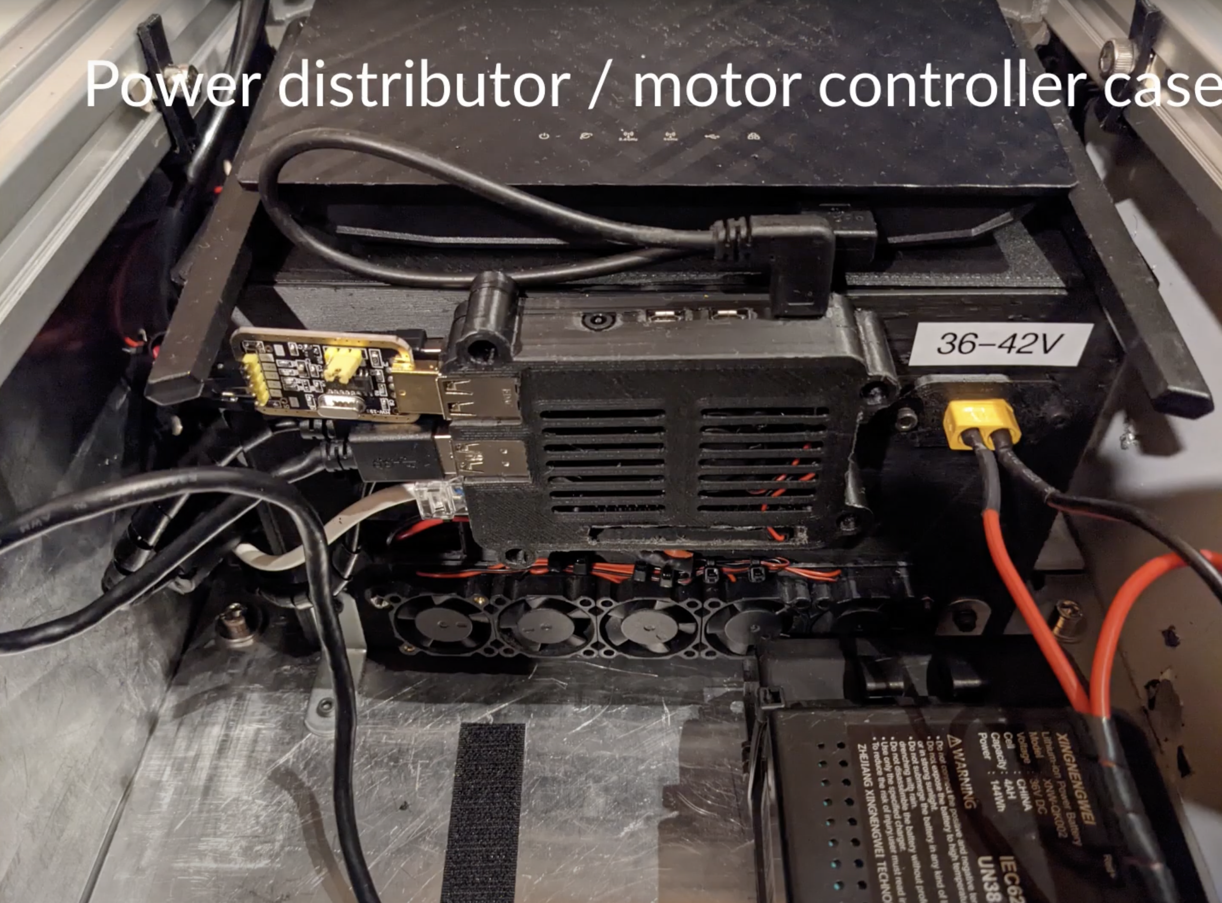
The Old Controller Box
The previous version of the controller box was poorly organized. Its primary purpose was to house the Raspberry Pi and the two ODrives, the essential hardware needed to operate the robot. The construction process was rather improvised: I initially printed a large enough enclosure for the ODrives, used 3D-printed mounts, and attempted to fit everything inside. Concerned about inadequate ventilation potentially damaging the ODrives, I cut an opening in the enclosure and hastily added some fans for airflow. There wasn’t enough space for the Raspberry Pi, so I resorted to attaching it to the exterior with double-sided tape, using a 3D-printed case from Thingiverse. While this setup was functional, it was visually unappealing and occupied more space than necessary. I had delayed designing a proper enclosure for the two ODrive boards and the Raspberry Pi, but now I finally have the result.

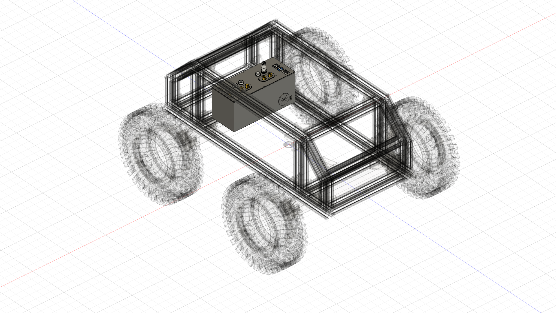
The New Controller Box
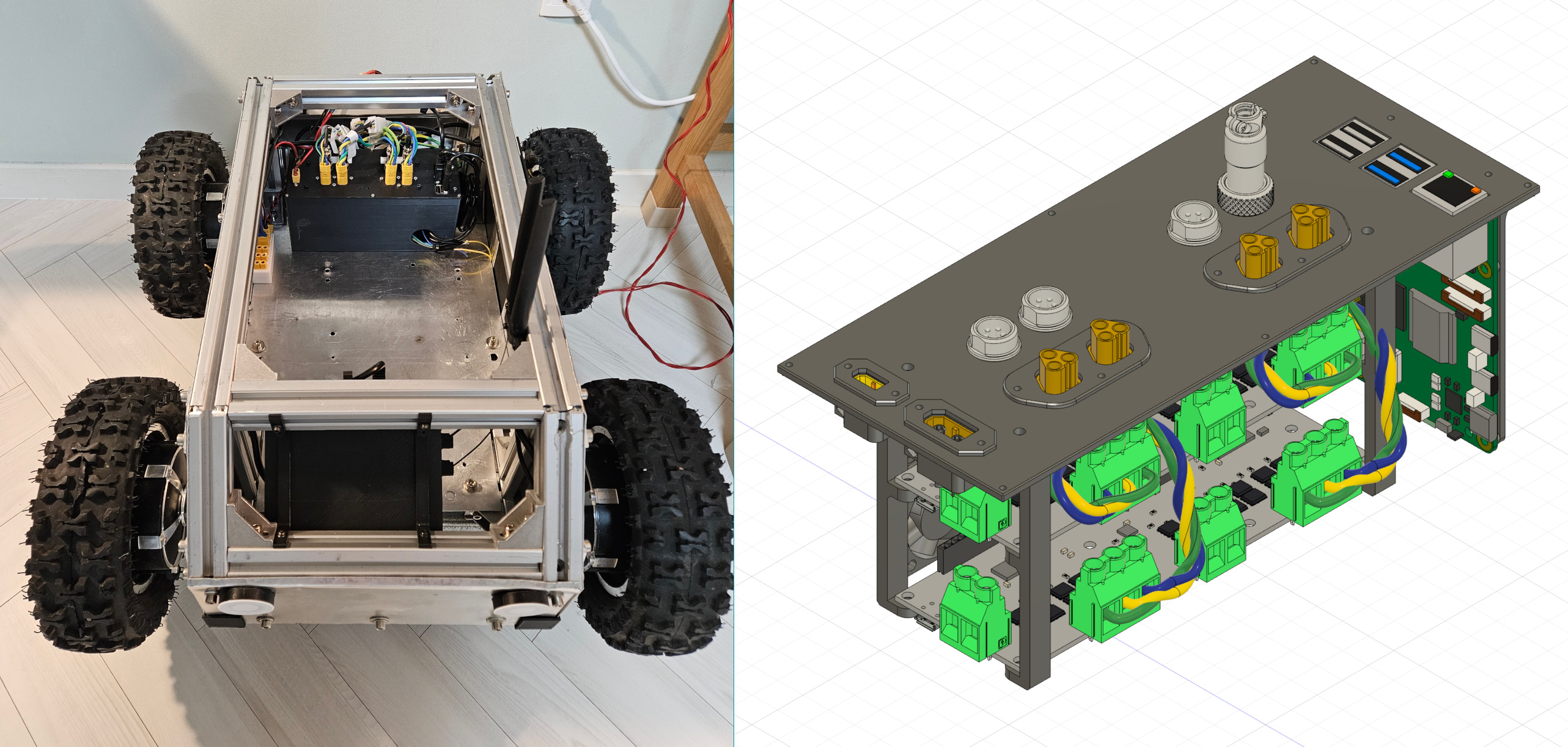
In designing the new controller box, my primary goal was to incorporate proper connectors for the BLDC motors, specifically for the three-phase wires and encoder wires. I chose MT60 connectors for the three-phase connections and GX12 5-pin connectors for the Hall effect encoder wires. The GX12 connectors are particularly advantageous because they screw in securely, preventing them from disconnecting during operation, which could lead to a hazardous spinout of the affected wheel. I also ensured there is a sufficiently large opening to accommodate any necessary cables, such as the USB cables connecting the ODrives to the Raspberry Pi and the e-stop connections plugging into the ODrive boards. Although the USB connections between the ODrives and the Raspberry Pi could be replaced with UART connections directly to the Raspberry Pi’s GPIO pins, I haven’t implemented this change yet.


The colored wires coming out of the big hole are for the E-stop and brake resistors (TBD).
Future Plans
Jetson Xavier AGX:
- come up with a proper case / mounting solution
- PCI multi usb hub?
- Unfortunately Nvidia stopped supporting this hardware (whowouldathunk???) but luckily jetson-containers makes it easier to run up-to date software stack.
IMU: I recently got a hold of a proper 9-axis IMU MW-AHRS-X1. Officially, only ROS2 is supported, but I found a ROS1 driver package for it and successfully ran it. Previously, I was using the built in IMU of the ZED camera, which has maximum 400Hz of IMU update. I should be able to get up to 1000Hz from the new IMU. Hopefully this would lead to better lidar inertial odometry.
Visual Navigation: try out https://github.com/robodhruv/visualnav-transformer
Revisit Lidar SLAM: test whether Multi-lidar FASTLIO2 will work with the combination of Livox Mid70 and a Velodyne VLP-16.
Robotic arm: LeRobot seems to be the new cool guy in robotics, and it’d be cool to play around with a robotic arm. The RoArm-M3 Pro seems like a decent choice - not too expensive and not too small. Seems to have ROS2 support as well. Seems to be comparable to the WidowX 250S but an order of magnitude cheaper.
- 650mm vs 500mm Reach
- 1300mm vs 1120mm Span
- 6 vs 5 Degrees of Freedom
- 250g vs 200g Payload