
SMUB
Super Mega Ultra Bot
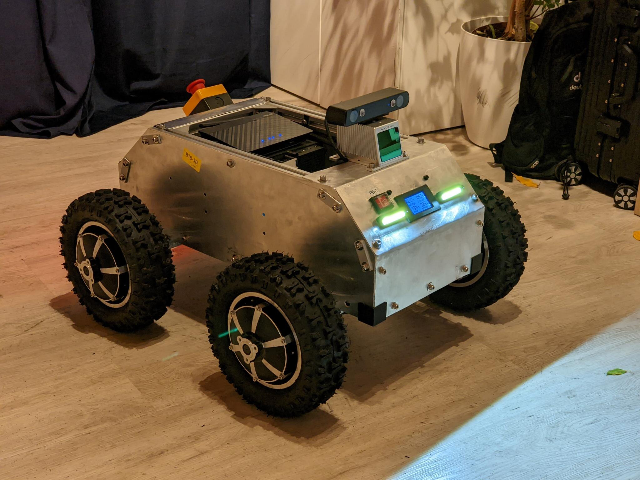
DIY 4x4 ROS-enabled rover robot with BLDC hub motors
In this article, we will be exploring the design and construction of SMUB, a DIY 4x4 ROS-enabled rover robot. The purpose of this project was to create a robotics research platform that was capable of traversing rough terrain, while also being small and lightweight enough to be easily transported and handled. I will be sharing the details of my design process, including the challenges and successes I encountered, in the hopes that it may be useful to others interested in building their own rover robots. Whether you are an experienced robotics professional or are just starting out in the field, I hope that my experiences and insights will be of value to you as you embark on your own projects.
Design and Materials
When designing SMUB, my main goal was to create a rover robot that was capable of traversing rough terrain and small enough for one or two people to lift. I wanted SMUB to be a viable home-built alternative to commercially available robots, such as the Clearpath Husky, that are often more expensive.
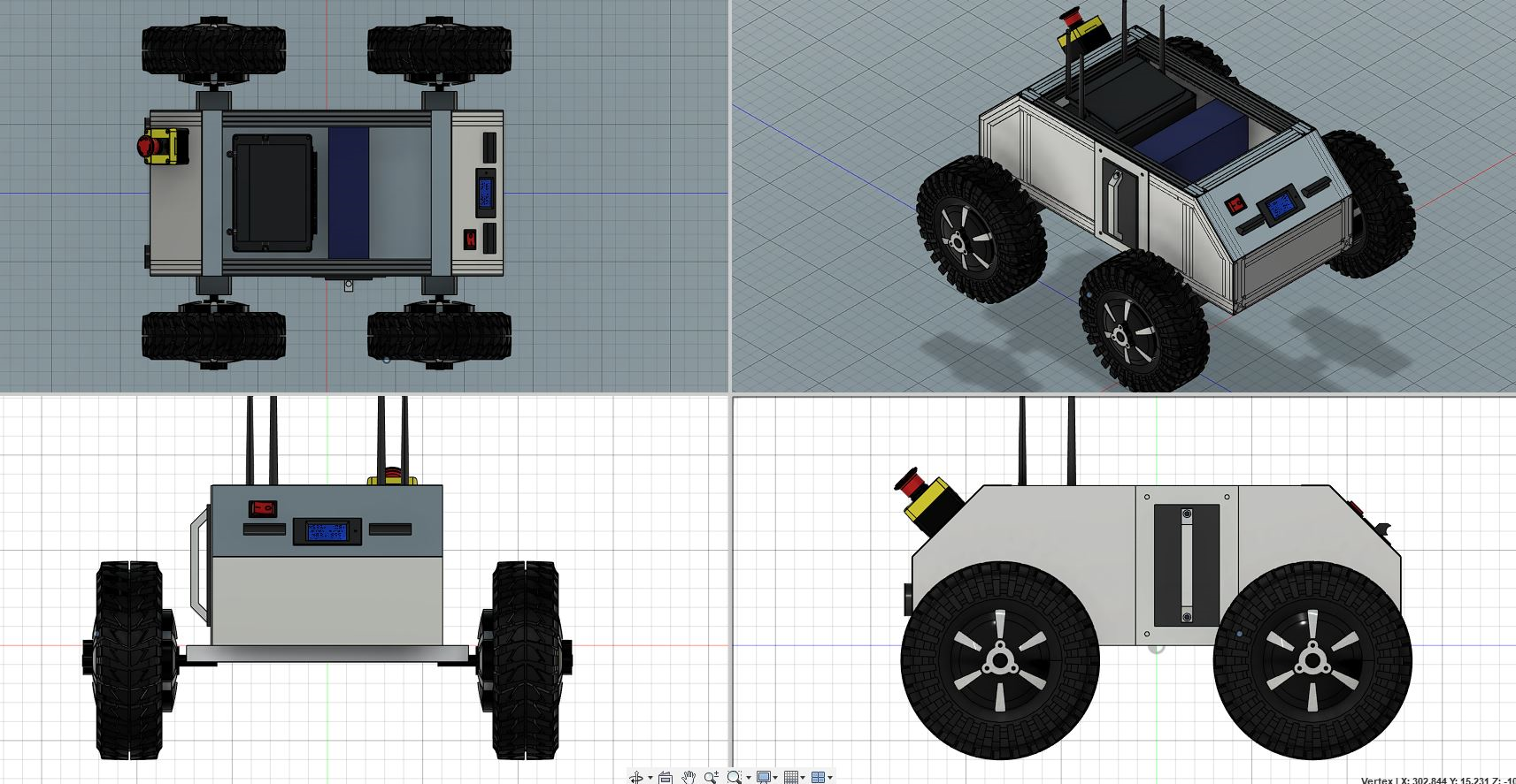
I used Fusion 360 to design and visualize the various components and features of SMUB. This included importing existing parts to get a sense of their size and dimensions, positioning and cutting the structural parts, and designing additional parts that had to be 3D printed. Fusion 360 was a valuable tool for ensuring that the various components of the robot fit together properly and functioned as intended.
The CAD file is available at here:
https://grabcad.com/library/super-mega-ultra-bot-1
For the structural part, I used a combination of strong and lightweight materials, including 30 cm x 30 cm aluminum extrusions for the frame, and 1 mm aluminum sheets for the surface.
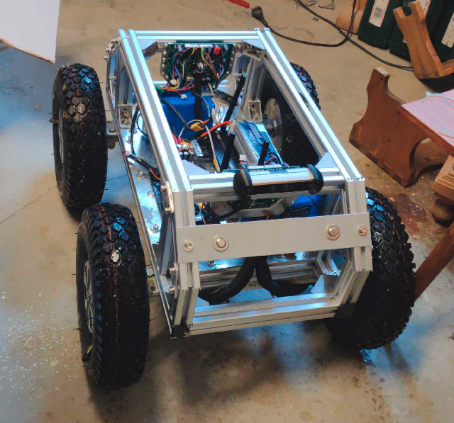
The aluminum extrusions were a good choice for the frame because they were strong, yet easy to cut and assemble using basic tools. I used brackets and T-slot nuts and bolts to join the extrusions together, forming a rigid and stable structure. I covered the surface of the robot with aluminum sheets to protect the electronics and provide a smooth and durable surface. To cut the sheets to size, I used a simple method involving a straight edge and a sharp knife.
In addition to the aluminum extrusions and sheets, I used a range of other materials and components to complete the robot. These included motors, sensors, computers, batteries, and various connectors and cables. I sourced most of these components from online retailers, such as ODrive Robotics, AliExpress, and Amazon. I also used 3D printed parts from Thingiverse to create custom mounting brackets and other components that were not available off-the-shelf.
Rough Bill of Materials
Note: some links are Amazon affiliate links.
| Item | Quantity | Description |
|---|---|---|
| 30x30 Aluminum extrusion | 4-5 m | Aluminum extrusions used for the frame of the rover robot |
| Extrusion brackets | 40 | Brackets and T-slot nuts & bolts used to connect the aluminum extrusions |
| Aluminum sheets | 2 sq. m | Aluminum sheets used to cover the surface of the rover robot |
| ODrive 3.6 (56V) | 2 | High-performance motor controllers used to control the motors and read sensor data |
| Capacitors (22uF) | 12 | Capacitors used to filter the hall signals and ensure smooth and accurate operation of the ODrive controllers (Refer to this discusssion on ODrive forum.) |
| Geared BLDC motors | 4 | High torque-to-weight ratio motors used to drive the wheels of the rover robot (13 inch, 48V version) |
| Single board computer | 1 | Onboard computer used to run custom software and communicate with other devices |
| FlySky FSi6B | 1 | Receiver & transmitter used to control the rover robot remotely using a radio controller |
| 48V battery | 1 | Battery used to power the rover robot |
| 48V-12V step down converter | 1 | Converter used to power advanced sensors and compute |
| 48V-5V step down converter | 1 | Converter used to power the Raspberry Pi and other peripherals |
| Neopixel Rings | 2 | LED light rings to be used as rear lights |
| Arduino Nano | 1 | For controlling the rear lights |
| 3D printed parts | As needed | Various 3D printed parts used for mounting and connecting components (https://www.thingiverse.com/nhooram/collections/smub) |
| Wires | As needed | Wires used to connect the various components of the rover robot |
| XT60 connectors | As needed | Connectors used to connect the battery and other components |
| Fans for cooling | As needed | Fans used to cool the electronics and motors |
| Emergency stop | 1 | An emergency stop switch used to safely shut down the rover robot |
| Switches | As needed | Switches used to control various functions of the rover robot |
| Nuts and bolts | As needed | To fasten things to other things |
Motors
One of the key considerations in the design of SMUB was the choice of motors. I initially experimented with hoverboard motors, but quickly realized that they did not provide enough torque, especially at lower RPM. Refer to this, this and this to see how hoverboard motors behave in a 4x4 skid-steer configuration with wheels of about 25cm diameter. In the 4x4 skid steer configuration, the hoverboard motors didn’t have enough torque in order to reliably overcome friction, especially when making tight turns.
In order to address this issue, I switched to geared BLDC motors, which offered a higher torque-to-weight ratio and better performance at lower RPM. These motors were purchased from Aliexpress and were a much better fit for my needs. They were able to handle the demands of rough terrain and skid steering.
| Model | phub-11hs |
| Motor type | in-hub geared BLCD motor, 15 poles |
| Gear | 5:1 ratio, planetary |
| Encoder | Hall |
| Voltage | 24V-48V |
| Power | 500W-800W |
| Torque | 70 Nm |
| Tyre size | 11 inch 11x3.50-6 tire |
| Speed | 0-12km/h |
| Suitable for | Trolleys / fruit carts / trucks/ Agricultural vehicle |
Electronics
The electronics of SMUB are an integral part of the robot’s functionality and performance.
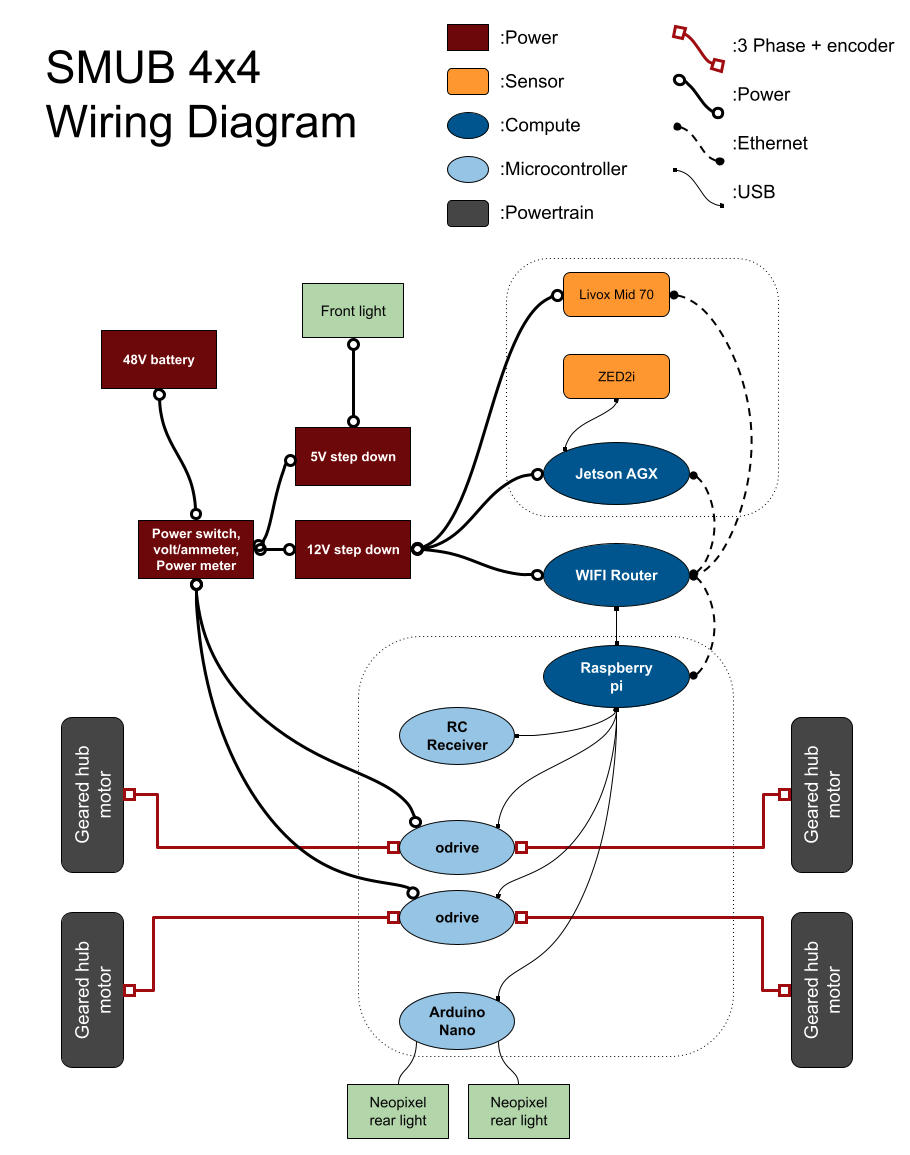
To run custom software and communicate with other devices, I used a Raspberry Pi as the onboard computer for communicating with the “hardware”, and a Jetson AGX for processing data from more advanced sensors and performing resource intensive tasks. The Raspberry Pi is a versatile single-board computer that can run a wide range of software and connect to various sensors and peripherals. The NVIDIA Jetson AGX is a high-performance computing platform designed for autonomous machines and robotics applications.
SMUB includes a wireless router, which allows multiple machines within the robot (such as the Raspberry Pi and Jetson AGX) to communicate with each other. This allows me to run multiple compute tasks on different machines and easily share data between them.
To read encoder sensor data and control the motors, I used ODrive controllers, which are high-performance BLDC motor controllers that support sinusoidal commutation and various encoders. I soldered on 22uF capacitors on the encoder pins to filter the hall signals and ensure smooth and accurate operation. Refer to this discusssion on ODrive forum. I wrote a ROS node for communicating with the ODrive controllers and controlling the wheels, as well as reading data from the encoders, voltage/current meter, and temperature sensors. This node was an important part of the control system, and allowed me to easily integrate the control system with the rest of the ROS stack.
I also included a FlySky FSi6B receiver that talks to the Raspberry Pi through a USB to TTL Adapter, which allows me to control the rover robot remotely using a typical hobby RC controller. I used this ROS package to publish cmd_vel using the RC controller. Refer to this page for more detailed information.
SMUB also includes a number of other electronic features to enhance its functionality and safety. These include an emergency stop switch, a front panel LCD voltage/current/power meter, and a small OLED display that can display any text I want to publish as a ROS message. The e-stop can be connected to the ODrive so that when the button is pressed, it pulls (and hold) nRST pin low on header J2.
To add a visual element to SMUB and make it more visible to others, I included a set of rear lights that could be controlled by an Arduino. I wrote a custom Arduino sketch that subscribed to the cmd_vel topic published by the robot’s onboard computer, and used the velocity and steering commands to mimic the behavior of a normal car. For example, if the robot was turning left, the left turn signal would flash yellow, and if it was turning right, the right turn signal would flash yellow. If the robot was moving in reverse, the reverse light would turn on.
Sensors
I won’t write too much about sensors in this post, but below is a list of different sensors I’ve integrated and tested on SMUB.
Cameras
- Realsense D435 (depth) + T265 (odometry)
- Stereolabs ZED2i (stereo depth)
- Ricoh Theta V (360 degree)
Lidars
- RPLidar A1 2d lidar
- Velodyne Puck
- Livox Mid 70
Summary
This article explores the design and construction of SMUB, a DIY 4x4 ROS-enabled rover robot. The robot is designed to traverse rough terrain while being small and lightweight enough to be easily transported and handled. The article details the design process, including the challenges and successes encountered, and provides a rough bill of materials. The article also discusses the choice of motors and electronics used in the robot, including the use of geared BLDC motors and a Raspberry Pi as the onboard computer. The CAD file for the robot is available on GrabCAD.